|
|
|
Hardware
* Joystick
This section details the materials needed and process to mount the joystick to the base.
 Materials Needed:
- A finished exterior base with frame- Check the previous base section for details.
- #1 Phillips screwdriver
- #4 x 3/8" flathead phillips screws
- A Power Drill
- Drill Bit- Skinnier sized
- Plexi-Glass (w/ template of layout)- Taken from steps in the Base section.
- 15/16" Wood spade- Used with the Power Drill to make a hole in the base to accomodate the stick.
- Joystick- Prefferably a Sanwa JLF stick like the stick from the VF4 set to the right.
If you don't have a Sanwa stick, you have to manipulate some of the
measurements and the joystick itself. Don't fret, it's easy.
Joystick Background
 Familurize yourself with the Joystick and it's parts. The joystick can be thought of as having 3 major parts- first, the clear
plastic guide; second, the PCB board / Microswitches; and third, the housing.
Familurize yourself with the Joystick and it's parts. The joystick can be thought of as having 3 major parts- first, the clear
plastic guide; second, the PCB board / Microswitches; and third, the housing.
The Plastic guide, which, in the JLF series
sticks from Sanwa has a square guide. Since there is a square opening, when you press the stick to the corners, you are
pressing 2 microswitches at a time (d/f, d/b, u/f, u/b). Obviously, pressing down will give you a down command; up an up
command; etc. The downside with having a square opening is that it's not as smooth for commands that require a circular, or
semi-circular motion, since the corner of the square produces a "notch" type action. You can feel this square with such
joysticks as Hori's various sticks, and Agetec / Ascii sticks. In fact, most consumer sticks that originate from Japan has
this square opening. 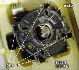 An 8 way angular guide (octagonal) shape guide is available from
Sanwa (GT-Y on the last page of the joystick section on Sanwa's site.) An 8 way angular guide (octagonal) shape guide is available from
Sanwa (GT-Y on the last page of the joystick section on Sanwa's site.)
The miroswitches, which usually are just clamped to the joystick with plastic housing. In the JLF's case, the micro-switches
are actually soldered on to a PCB board. The PCB board has a 5 pin male receptacle, which is the (ground, up, down, left, and
right) functions. Retracing the copper traces from each pin leads you to which miroswitch it is comming from.
The housing holds together the various parts, as well as having the spring, the e-clip, etc. The e-clip holds together
the shaft (I know, this seems "phallic",) and spring assembly together. Removing the e-clip also reveals the bowl shaped
piece that acts as a ball-bearing. This piece is plastic for the JLF sticks, but Sanwa does offer sticks with a more durable
steel bearing. The friction from the rubbing of the bearing with the plastic housing wears the bearing, if it is not
lubricated with silicon grease; especially if dirt and debris gets in there.  The parts to the right are from a Hori Playstation Namco stick. Notice it doesn't have the PCB board. The micor swithces
are housed on the white, square, plastic housing.
The parts to the right are from a Hori Playstation Namco stick. Notice it doesn't have the PCB board. The micor swithces
are housed on the white, square, plastic housing.
Steps:
- Use the template of the joystick and
pusbutton layout that is still taped on the bottom side of the plexiglass, and put it on the base. Drill a pilot-hole
for the joystick through both the base and the plexiglass, using a skinnier drill bit. The pilot-hole is the guide for the
wood spade.
- Now use the wood spade to cut a hole in the base for the opening of the joystick.
- After you cut the hole in the base, go on to the joystick, and remove the PBC board and guide by pushing the 4 pins in. The pin locations are pointed out with a picture above.
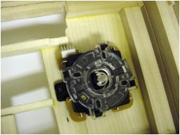
- Now take the black plastic housing (no need to remove the e-clip) and srew
- Mount the plastic housing to the base with $4 x 3/8" screws, prefferably phillips type. DO NOT DRILL PILOT HOLES.
Just press down hard and keep turning the #1 screwdriver. Mount the housing of the stick as as shown:

- Now replace the PCB board with the 5-pin receptacle towards the back of the base. This is important if you do not
understand the importance of the direction of the microswitches. If you understand the concept of the joystick's PCB, you
can replace the PCB with the 5-pin receptacle facing anywhere. The importance of the direction of the 5 pin receptacle will
be discussed in the Wiring section.
- Lastly, replace the clear plastic guide.
The final product:
|
|

|