ELECTRONICS
* Background Knowledge
This section covers the electronics of the joystick- giving some basic information on circuits, and most importantly,
how to wire the circuit board that is the brains to the josytick.
What is a circuit board
The circuit board, or pcb
converts input, which are the button presses and joystick movements done by your manipulation of the input device- the joystick.
The circuit board converts this information to a digital one which the console can read and understand. The components on
the board are connected to the board via solder, which is tin and some other impurities, which when heat is applied to it,
melts and can act as a weld. The board itself is made of a non-conducting (electricity, actually current, cannot
flow through) material- silicon. The brass colored lines you see on the surface of the board are called traces
and are made of copper. Copper is a conductive material,
meaning current can flow through it. Most wire are made of copper because of its relatively low cost.
A basic primer to the concept of an electronic circuit
What are circuits? It's a continuous loop from point A to point B. Think of it
as a race track. It can be oval, circle, square, or any shape. This continuous loop is called a
closed circuit.
Instead of race cars,
on electronic circuits, you have current that races around on copper traces. A power source
such as a battery provides the current. Current starts from a power source's positive terminal (point A)
and travels to it's negative terminal, which is also known as ground (point B).
When conducting material such as copper connects both terminals, it makes a closed, working, circuit.
Current runs continuously on a closed circuit. But when you put a gap in the circuit,
or cut the circuit, you interrupt the circuit, not allowing current to flow to ground. This is called an
open circuit. Again, current cannot flow in an open circuit because of the gap or break.
A closer look at the PCB board
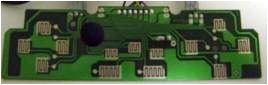
 The copper seen on this PCB board has
been shaped to form many circuits. Each one of these circuits are assigned a function, in this case
(the board is from an Interact Playstation controller)- UP, DOWN, LEFT, RIGHT, SQUARE, CIRCLE, TRIANGLE,
X, L1, L2, R1, R2, SELECT, and lastly- START. The power, or current, comes from the console itself.
Additionally, the circuit must also must be in contact with a GROUND point to complete the circuit. Notice
that the circuits here are all OPEN.
When you press a button or
directional button on a joypad or joystick, you are filling in the gap with conducting material, thus,
closing and connecting the circuit, allowing current to flow through the circuit. When this current flows
in a given circuit, it sends a signal to the console that you are inputting a command through the controller.
The copper seen on this PCB board has
been shaped to form many circuits. Each one of these circuits are assigned a function, in this case
(the board is from an Interact Playstation controller)- UP, DOWN, LEFT, RIGHT, SQUARE, CIRCLE, TRIANGLE,
X, L1, L2, R1, R2, SELECT, and lastly- START. The power, or current, comes from the console itself.
Additionally, the circuit must also must be in contact with a GROUND point to complete the circuit. Notice
that the circuits here are all OPEN.
When you press a button or
directional button on a joypad or joystick, you are filling in the gap with conducting material, thus,
closing and connecting the circuit, allowing current to flow through the circuit. When this current flows
in a given circuit, it sends a signal to the console that you are inputting a command through the controller.
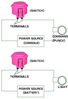 An example of a simple circuit is a flashlight. The ground point is the metal piece on the light bulb,
which is also the metal base. One end of the battery is connected to the ground by copper. This
ground piece is also connected to one end of the light fillament. The other
end of the battery is connected to the other end of the fillament, completeing (closing)
the loop, lighting the
light bulb, making the flashlight work. WHEN YOU FLIP THE SWITCH ON THE FLASHLIGHT, YOU ARE MAKING
A GAP (open) IN THE CIRCUIT. This will off the flashlight. When you flip the switch on the flashlight, what
you are actually doing is moving a piece of conductor that connects the circuit loop to on it, and flip it
again to off it- theoretically connecting the circuit, and disconnecting the circuit
with the switch. For the above diagram, pressing the pink button will "close" the circuit
to cause a "punch" (top example).
For the bottom example, pressing the button will again, close the circuit and light the bulb.
An example of a simple circuit is a flashlight. The ground point is the metal piece on the light bulb,
which is also the metal base. One end of the battery is connected to the ground by copper. This
ground piece is also connected to one end of the light fillament. The other
end of the battery is connected to the other end of the fillament, completeing (closing)
the loop, lighting the
light bulb, making the flashlight work. WHEN YOU FLIP THE SWITCH ON THE FLASHLIGHT, YOU ARE MAKING
A GAP (open) IN THE CIRCUIT. This will off the flashlight. When you flip the switch on the flashlight, what
you are actually doing is moving a piece of conductor that connects the circuit loop to on it, and flip it
again to off it- theoretically connecting the circuit, and disconnecting the circuit
with the switch. For the above diagram, pressing the pink button will "close" the circuit
to cause a "punch" (top example).
For the bottom example, pressing the button will again, close the circuit and light the bulb.
Switches & Pushbuttons
 What you must understand about joysticks and console controllers is that they are made up of
MOMENTARY SWITCHES and PUSHBUTTONS, some of them are also known as NORMALLY OPEN SWITCHES and
PUSHBUTTONS. The switches and pusbuttons have two terminals (connectors) that you connect to two
open points in a circuit. Since the switch and buttons are normally open, the only time the circuit will
flow with current is when you close the circuit by pressing the switch or button. When you let go of the
switch, or release the pusbutton, the circuit is again, open. What this means
is that the ciruit for each input (Up, Down, Left, X, O, Select, etc.) are normally open, meaning they
have a gap in them. When you push the joystick, or a button, what you are doing is closing the circuit,
filling the gap, making current flow around the circuit, which signals the console to do your specific
command. The shown switch above has 3 terminals. One is to connect to one side of the open in a circuit,
while the other two terminals are to choose if you want a "normally open" or "normally closed" switch.
Connect the other side of the open circuit to the terminal labeled "NO" which stands for Normally Open.
Choosing "NC" or NOrmally Closed will make the switch open when pressed. Again, the circuit will be closed when
unpressed, and open when pressed- opposite of Normally Open.
What you must understand about joysticks and console controllers is that they are made up of
MOMENTARY SWITCHES and PUSHBUTTONS, some of them are also known as NORMALLY OPEN SWITCHES and
PUSHBUTTONS. The switches and pusbuttons have two terminals (connectors) that you connect to two
open points in a circuit. Since the switch and buttons are normally open, the only time the circuit will
flow with current is when you close the circuit by pressing the switch or button. When you let go of the
switch, or release the pusbutton, the circuit is again, open. What this means
is that the ciruit for each input (Up, Down, Left, X, O, Select, etc.) are normally open, meaning they
have a gap in them. When you push the joystick, or a button, what you are doing is closing the circuit,
filling the gap, making current flow around the circuit, which signals the console to do your specific
command. The shown switch above has 3 terminals. One is to connect to one side of the open in a circuit,
while the other two terminals are to choose if you want a "normally open" or "normally closed" switch.
Connect the other side of the open circuit to the terminal labeled "NO" which stands for Normally Open.
Choosing "NC" or NOrmally Closed will make the switch open when pressed. Again, the circuit will be closed when
unpressed, and open when pressed- opposite of Normally Open.
Everyday Objects
You actually interact with switches everyday- the light switches in the house or apartment. Also, you
right now are in front of alot of "normally open" switches or pushbuttons- the keyboard keys, when pressed,
close the circuits under the keypads, which trigger a command to the computer.
 The FUN Begins
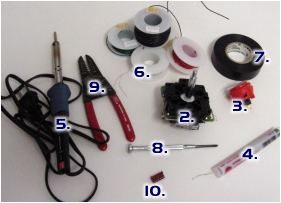
Materials needed
- A controller to hack the PCB board
- Joystick
- Pushbuttons
- Solder
- Soldering Iron
- 24 Guage wire
- Electrical Tape
- A presision Phillips Screwdriver
- Wire Stripper and Cutters
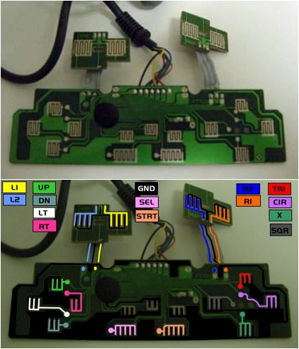 The PCB to the right is from an Interact Playstation controller. In the colored diagram, the blacked area
is connected to ground. The various colors represent circuits connected to the various functions of the
Playstation controller. When a colored area, such as the red area touches ground with the help of a
conductor, closing the circuit- it activates the TRIANGLE button function on the Playstation. Notice
that ground is the common "closer." It when you look under the buttons, you will notice the conductor that
connects both the ground and the wanted circuit when the button or direction is pressed. Also, notice
that the three ciruits above Select and Start are not used. These were turbo, clear and, slow functions.
You can easily add these functions to your joystick.
The PCB to the right is from an Interact Playstation controller. In the colored diagram, the blacked area
is connected to ground. The various colors represent circuits connected to the various functions of the
Playstation controller. When a colored area, such as the red area touches ground with the help of a
conductor, closing the circuit- it activates the TRIANGLE button function on the Playstation. Notice
that ground is the common "closer." It when you look under the buttons, you will notice the conductor that
connects both the ground and the wanted circuit when the button or direction is pressed. Also, notice
that the three ciruits above Select and Start are not used. These were turbo, clear and, slow functions.
You can easily add these functions to your joystick.
Take note though of the green film that covers the circuit. You need to soder the wire to the PCB
board where there is no green film, or you can expose the copper underneath by removing the film where
you want to make a connection.
Soldering the wire on the PCB board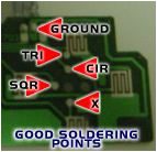
 What you are doing when you solder wire to the PCB board, and connect them to pushbuttons, you are extending
the circuit to your desired length- which is to reach the surface of where you want to mount the pushbuttons.
Make sure your wire is long enough to extend from the location of the PCB board on the base of your
joystick, to the location of where you mount the joystick, or pushbuttons. I've detailed in the diagram
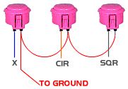
where good places are to solder your wire. You only need one ground point on the PCB board, and you can
daisy chain the ground to your pushbuttons shown in the diagram to the left. Repeat wiring the
pushbuttons for the Start and Select buttons as shown above. Yes, you can just connect the ground wire
to the ground connection on any of the pushbuttons.
What you are doing when you solder wire to the PCB board, and connect them to pushbuttons, you are extending
the circuit to your desired length- which is to reach the surface of where you want to mount the pushbuttons.
Make sure your wire is long enough to extend from the location of the PCB board on the base of your
joystick, to the location of where you mount the joystick, or pushbuttons. I've detailed in the diagram
where good places are to solder your wire. You only need one ground point on the PCB board, and you can
daisy chain the ground to your pushbuttons shown in the diagram to the left. Repeat wiring the
pushbuttons for the Start and Select buttons as shown above. Yes, you can just connect the ground wire
to the ground connection on any of the pushbuttons.
Wiring the Joystick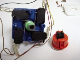
The joystick is configured with switches sandwiched in between two parts of the joystick base. In this
case, each switch has only 2 terminals.
Any one can be used to connect to common ground, which can also be daisy chained to any other ground on
any circuit, including the ground on the pushbuttons. The other terminal is connected to UP, DOWN,
LEFT, and RIGHT, respectively. Remember though, when you press up on a stick, the stick is
actually pressing the switch on the bottom. When you press down on a stick, the stick is pressing the
switch on top. The Left and right switches are not affected by this "mirroring." Also, when you
press a diagonal direction on the joystick such as DOWN/LEFT, you are actually pressing two switches
at the same time.
Use Recepticles Instead of Solder
 Instead of using soldering on the wires to the pushbuttons and joystick switches, you can use recepticles.
These require a crimping tool to connect to the end of the wire to the recepticle
so you can easily disconnect the wires
in case you need to, instead of having the hassle of reheating and sucking the solder off the wire later.
Instead of using soldering on the wires to the pushbuttons and joystick switches, you can use recepticles.
These require a crimping tool to connect to the end of the wire to the recepticle
so you can easily disconnect the wires
in case you need to, instead of having the hassle of reheating and sucking the solder off the wire later.
Some Soldering Tips
When using solder, apply heat to the wire with the soldering iron, and press the solder wire against the
wire which requires soldering. Use a damp sponge to ocasionally wipe the residue that builds up on the soldering
iron.