ELECTRONICS
* Terminals
This section covers the wiring of the joystick and pushbuttons to a 15-pin female terminal, as well as wiring a
controller PCB to a 15-pin male terminal.
Wiring Diagrams
This is a diagram and basis for how you will wire your joystick.
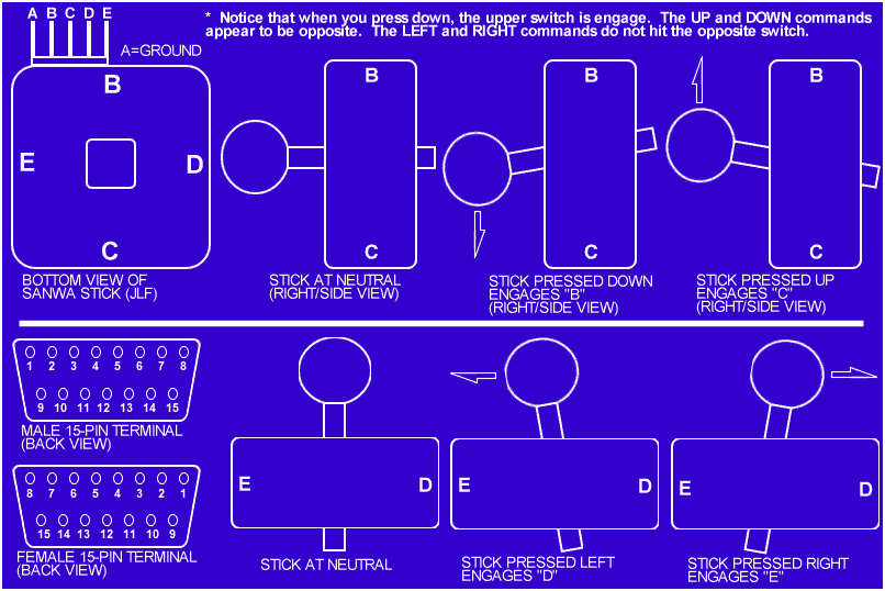
The diagram above assumes that the 5 pin terminal on the joystick is pointing towards the back of the joystick.
Looking at the diagram, "B" is "DOWN," "C" is "UP," (yes, it's reversed... think about this), "E" is "LEFT," and "D" is
"RIGHT." If you
have the terminal pointing to any other side, the directions you press will not match the orientation of the diagram. Say that
you install the PCB board with the 5-pin terminal to the right, viewing the stick from the bottom. "E" then becomes "DOWN,"
"D" becomes "UP," "C" becomes "LEFT," and "B" becomes "RIGHT." Essentialy, the directions shifted over 90 degrees. So you
can actually have the pins pointing any direction. For those that do not understand, just mount the joystick on the base
with the pins pointing to the back and use the following pin assingments.
Pin Assignments
 You can assign any command to any one of the 15 pins on the 15-pin Female Terminal. It's up to you if you want the Female
or Male terminal on the base. Remember to write down what pin is assingned what command, because you will need it when you
wire the Male terminal to the PCB board of a controller. Here is my pin assignments that
I use.
You can assign any command to any one of the 15 pins on the 15-pin Female Terminal. It's up to you if you want the Female
or Male terminal on the base. Remember to write down what pin is assingned what command, because you will need it when you
wire the Male terminal to the PCB board of a controller. Here is my pin assignments that
I use.
| PLAYSTATION PIN ASSIGNMENTS |
|---|
| Pin Number | Command |
|---|
| 1 | UP (*C) |
|---|
| 2 | DOWN (*B) |
|---|
| 3 | RIGHT (*D) |
|---|
| 4 | LEFT (*E) |
|---|
| 5 | BOX |
|---|
| 6 | X |
|---|
| 7 | CIRCLE |
|---|
| 8 | TRIANGLE |
|---|
| 9 | L1 |
|---|
| 10 | R1 |
|---|
| 11 | L2 |
|---|
| 12 | R2 |
|---|
| 13 | SELECT |
|---|
| 14 | START |
|---|
| 15 | GROUND (*A)** |
|---|
 *denotes the pins from the joystick given from the wiring diagram. *denotes the pins from the joystick given from the wiring diagram.
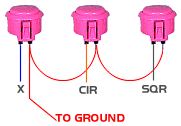
**denotes that this is common ground. The ground wires from the pushbuttons will also go to this pin. Remember, you
can daisy chain the wires on the pushbuttons (daisychaining is explained in the Electronics/Basics section.) |
 Solder wire from the pins on the 15-pin terminals to the 5-pin terminal on the
joystick according to the chart. I recommend getting a 5 wire harness from Sanwa that allows for easy disconnect from the termials.
Use recepticles for wires to the pushbuttons for a quick way to disconnect the wires. I personally use 24 guage wire
on the sticks I build.
Again, you may change pin assignments if you wish, just remember which pin is which. Wire the PCB from the controller
discussed in the (Electronics/Basic) section according to this chart.
Solder wire from the pins on the 15-pin terminals to the 5-pin terminal on the
joystick according to the chart. I recommend getting a 5 wire harness from Sanwa that allows for easy disconnect from the termials.
Use recepticles for wires to the pushbuttons for a quick way to disconnect the wires. I personally use 24 guage wire
on the sticks I build.
Again, you may change pin assignments if you wish, just remember which pin is which. Wire the PCB from the controller
discussed in the (Electronics/Basic) section according to this chart.
Making a custom box for the controller PCB board.
Materials needed
- A controller PCB board
- A Project Box
- Xacto Knife
- #1 Screwdriver
Buy the plastic project box from Radio Shack. They have all types of sizes to accomodate the size of PCB board you want
to house. Score the shape of the back end of the 15 pin terminal on the project box with the back-side of an Xacto Knife,
Score it deep enough so you can use pliers to rip off the unwanted piece of plastic, without ruining the box.